What Are the Different Types of Joints in Welding?
americanindustrialsupl and its partners may earn a commission if you purchase a product through one of our links.
When it comes to welding, one of the most critical aspects to understand is the different types of joints in welding that are utilized to create strong and durable welded structures. The joint is where two pieces of metal are fused together through the welding process. Selecting and properly preparing the right type of joint for an application is key to achieving a high-quality and long-lasting weld. That’s why having knowledge of the various joint configurations and options is so important for welders and anyone involved in welding design or welding training.
In this article, we will explore the primary categories and classifications of welding joints. We’ll look at the distinguishing features of each joint type, considerations for joint preparation and design, typical applications where certain joints excel, and how these joints are commonly used with processes like gas welding, arc welding, MIG welding, and TIG welding. Gaining familiarity with joints like the butt, lap, tee, corner, and fillet can pay dividends in creating optimal welds for any project.
We’ll also consider specialized joints like the seam, plug, and backing welds. Lastly, we’ll examine how proper joint design and adherence to industry welding standards further ensures the strength, quality, and safety of welded structures across manufacturing, construction, and other domains.
Types of Welding Joints
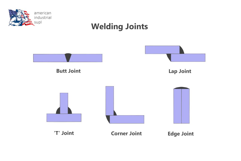
There are of course many different types of joints in welding that you can apply for various applications. Below we look at the ones that you are most likely to come across as well as consider a few other less utilized jointing methods.
Butt Joint
The butt joint is one of the most fundamental and frequently used joints in welding. It is formed when two pieces of metal are aligned and joined together along their edges. The aligned edges are referred to as the “toe” and “root” of the joint.
Butt joints are versatile and can be used to join metals of various thicknesses. They are an excellent choice for joining sheet metal, plate metals, structural steel, and piping materials. Some key advantages and uses of the butt joint include:
- Used extensively in structural steel construction and fabrication.
- Creates seamless, strong joints for joining long members or flat plates.
- Minimal joint preparation needed compared to other joints.
- Allows for complete joint penetration when welded.
- Often used in applications like shipbuilding, boilers, storage tanks, and pipelines.
When welding a butt joint, proper joint preparation is important to ensure weld quality. Some key preparation steps include:
- Securing metals in proper alignment using jigs, fixtures or clamps.
- Creating a small root gap usually 1-3mm to allow penetration.
- Beveling the edges at an appropriate angle (usually 30-60°) to ensure fusion.
- Using a backing strip or back gouging to create full penetration welds.
Butt joints can be welded in various positions and are compatible with most major welding processes like shielded metal arc welding (SMAW), gas metal arc welding (GMAW), flux cored arc welding (FCAW) and gas tungsten arc welding (GTAW).
Lap Joint
The lap joint is formed when two overlapping metal plates are joined through welding. The overlap area between the two plates is referred to as the lap.
Lap joints are extensively used for joining sheet metal components and materials under 6mm thickness. Some applications and advantages include:
- Sheet metal ducting, tanks, cabinets, and enclosures.
- Low-stress household appliances and furniture.
- Thin sections and plates difficult to weld with other joints.
- Only single-sided welding access required.
- Quick to prepare with minimal joint cleaning.
The amount of overlap and welding approach can vary depending on material thickness and welding process used. Some best practices for lap joints include:
- Overlap of 1.5-2x material thickness for thinner sheets.
- Welding along both edges of overlap for maximum strength.
- Allowing gaps for gas flow if welding encapsulated area.
- Using fillet welds for improved strength over lap seam welds.
Lap joints are compatible with gas welding, arc welding, TIG, and MIG processes. They can also be resistance welded or brazed depending on application. Care must be taken to avoid over-penetration and burning through base metals.
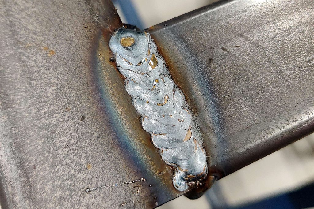
Tee Joint
The tee joint, also known as the T-joint, is formed when two metals are joined perpendicularly to create a “T” shape. This type of joint provides strong right angle connections.
Tee joints have some important structural applications and advantages:
- Connecting braces, frames, supports and stringers.
- Joining rails for stairs, balconies, platforms.
- Providing rigid, load-bearing corner joints.
- Ability to weld both sides for full penetration.
For load-bearing applications, properly preparing the joint is critical. Some guidelines include:
- Prior machining for close fit-up and precise angles.
- Beveling edges to ensure weld penetration into the root.
- Using backing strips or tabs for supporting underside.
- Leaving adequate gaps for welding access.
Tee joints lend themselves well to fillet welds along the intersection. Groove welds may also be used depending on joint design. Compatible processes include stick welding, MIG, and TIG welding.
Corner Joint
The corner joint is a basic joint type formed when two metals meet and are welded at an angle of approximately 90 degrees. This creates a sturdy right-angled corner connection.
Some typical applications for the corner joint include:
- Structural frames and bracing
- Table, desk, and furniture corners
- Window, door, and cabinet frames
- Platforms, railings, and safety cages
Corner joints are most often configured in either a single-bevel or double-bevel style. Single-bevel is suitable for lighter applications, while double-bevel provides the highest strength and weld penetration for structural joints.
Proper joint preparation steps for a high-quality corner connection include:
- Cutting/machining the metal pieces to achieve close fit-up at the corner.
- Beveling both edges at 30-45° to allow weld access and penetration.
- Tack welding parts in place and confirming alignment.
- Optionally adding a backing strip for support.
The most common welding techniques for corner joints are:
- Fillet welds – suitable for lighter single-bevel joints. Allows welding from one side.
- Groove welds – provides full penetration on double-bevel joints for maximum strength.
Both MIG and stick welding work well for corner connections. TIG can be used but is slower. Gas welding is only suitable for thin materials.
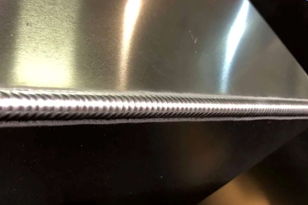
Edge Joint
The edge joint refers to the weld joint formed by two metal components coming together and joining along their edges to create a continuous seam. This type of joint is generally seen in sheet metal fabrication.
Key features and applications of edge joints:
- Allows creating leakproof seals along adjoining edges.
- Used to construct ducting, tanks, pipes, boilers, and other enclosed structures.
- Enables extended flat or curved seams through sequential welding.
- Works well for sealing lighter gauge sheet metals and plates.
Proper preparation is vital for quality edge welds:
- Metals must align evenly with no gaps between edges.
- A tight fit-up is necessary to ensure full weld penetration.
- Edges may need to be beveled to improve penetration.
- Typically welded in a flat position for accessibility.
Edge joints are widely compatible with other welding methods:
- Gas metal arc welding (GMAW) and gas tungsten arc welding (GTAW) enable fast seam welds.
- Shielded metal arc welding (SMAW) allows robust welds but slower.
- Oxy-fuel welding works for thinner materials.
Fillet Weld
The fillet weld is a versatile corner joint created by depositing weld metal in the internal angle between two pieces of metal that are joined at an approximate right angle. The triangular weld deposit itself is called the fillet.
Fillet welds have become ubiquitous in fabrication and manufacturing because of their flexibility and strength. Typical applications include:
- Connecting structural steel members.
- Joining perpendicular braces and supports.
- Providing overlap welds on lap joints.
- Attaching lugs, brackets, and plates.
Benefits of the fillet weld:
- Only requires access from one side to deposit weld.
- Can join metals of varying thicknesses.
- Offers good strength in all loading directions.
- Relatively simple to execute with automatic welding.
Standard processes for fillet welds are GMAW, FCAW, and SMAW. The size of the fillet is specified based on the leg length as measured from the joint root. Following applicable welding codes helps ensure proper weld quality and strength.
Groove Weld
The groove weld is a widespread joint type that involves welding two pieces of metal together within a prepared groove between them. This provides deep, penetrative welds that fully fuse the joint.
Groove welds are ideal for joining thicker metals where high strength is needed. Typical applications:
- Structural steel in buildings, bridges, and equipment.
- Heavy machinery parts and frames.
- Large pipes, pressure vessels, boilers, and tanks.
- Load-bearing beams, axles, shafts, etc.
Effective joint preparation is critical for groove welds:
- Edges must be beveled at an angle (usually 30-60°) to create a deep groove.
- A root face is left to support and control penetration.
- Root opening (gap) should align with welding process used.
- Backing strips may be used to support.
Groove welds can utilize various techniques:
- Single-pass – Shallow welds offering lower strength.
- Multi-pass – Successive layers for deeper penetration.
- Full penetration – Highest strength option with complete fusion.
Usual welding methods include SMAW, GMAW, FCAW, SAW, and GTAW. Following proper welding standards ensures optimal joint integrity.
Plug Weld
The plug weld is very useful forjoining overlapping sheets and plates. It is made by drilling or punching a hole into the upper component, then welding through this hole onto the lower component. The weld “plug” fills the hole.
Plug welds offer several advantages:
- Allow welding of overlapped sheets that can’t be edge welded.
- Provide leak-free connections between layers.
- Cause minimal distortion compared to long seam welds.
- Enable welding in situations with limited access.
Some key considerations for sound plug welds include:
- Hole diameter should be roughly 1.5x material thickness.
- Spacing holes appropriately based on design loads.
- Ensure good weld penetration into lower layer.
- Use backing strip if accessible from back side.
Plug welding is very versatile for joining:
- Sheet metal ducts, tanks, machinery guards.
- Overlapping structural steel plates.
- Multilayer electrical enclosures and chassis.
- Automotive panels, frames, exhaust components.
It can be performed with standard processes like GMAW, FCAW, and SMAW. Following codes for size and spacing ensures proper weld strength.
Slot Weld
The slot weld is a spot welding technique where the weld is deposited within an elongated slot or channel between two overlapping sheet metals. This provides intermittent welds with good strength.
Key features and uses of the slot weld:
- Allows leakproof welding of overlapped sheets with minimal distortion.
- Frequently used in sheet metal ductwork, tanks, mufflers, and machinery guards.
- Enables welding sheets where continuous long seams are impractical.
- The slot provides space for gas ventilation and weld access.
Proper steps for quality slot welds include:
- Cutting/grinding straight, uniform slots in top sheet.
- Spacing slots appropriately based on design loads.
- Welding deeply into slot with full penetration to lower metal.
- Employing techniques like weaving for thorough fusion.
Slot welds work well for lighter gauge metals under 3mm thickness. Compatible welding processes are:
- Gas metal arc welding (GMAW) – Offers faster, deeper welds in slots.
- Flux cored arc welding (FCAW) – High deposition rate.
- Shielded metal arc welding (SMAW) – Versatile but slower speed.
Following sheet metal codes helps determine optimal slot size and spacing for the design.
Here is 750 words for Section II Sub-sections J, K, and L:
Seam Weld
The seam weld refers to a continuous weld created along an extended joint where two materials meet. It produces an unbroken, leak-tight connection along the seam.
Some typical applications and uses of seam welds include:
- Joining sheet metal to construct pipes, tubes, tanks, ducts, and hydraulic cylinders.
- Sealing box-type structures like containers, cabinets, and silos.
- Fabricating boat and ship hulls, storage tanks, and other vessels.
- Leakproof welding of pipelines, boilers, pressure vessels.
Effective techniques for quality seam welds include:
- Ensuring joint surfaces are smooth, even and aligned prior to welding.
- Using jigs and fixtures to hold parts in consistent positions.
- Employing weave, stringer bead, and back-step welding motions for proper fusion.
- Overlapping beads slightly to cover joints fully.
- Visually inspecting/non-destructively testing welds for defects.
Compatible welding processes for seams are:
- Gas metal arc welding (GMAW) – Offers higher deposition rates for faster welding.
- Flux cored arc welding (FCAW) – Deep penetration ideal for thick materials.
- Gas tungsten arc welding (GTAW) – Provides high-quality welds for critical applications.
Surfacing Weld
A surfacing weld involves depositing a layer of weld metal over a base material to provide a wear-resistant surface and protect against corrosion, impact, and abrasion. This is also referred to as a hard-facing weld.
Key applications for surfacing welds include:
- Applying wear plates to excavating equipment, bulldozer blades, truck beds.
- Protecting valve seats, pump casings, pipes against erosion.
- Building up bearing surfaces on shafts, rollers, and screws.
- Restoring dimensions to worn parts like gears or sprockets.
Surfacing techniques include:
- Using specialized hard-facing alloys optimized for wear and impact resistance.
- Employing stringer, weave, and overlapping beads for 100% coverage.
- Building up overlay to specified thickness based on service conditions.
- Adhering to preheat and inter-pass temperature limits of base metal.
Compatible welding processes are:
- Shielded metal arc welding (SMAW) – Most often using flux-coated hard facing electrodes.
- Gas metal arc welding (GMAW) – Offers faster deposition rates.
- Flux cored arc welding (FCAW) – Self-shielding ability is advantageous.
- Plasma transferred arc (PTA) – Automated surfacing of large components.
Backing Weld
A backing weld is a weld placed on the underside or second side of a welded joint and is designed to support and strengthen the root of the primary weld. It helps achieve full penetration welds.
Applications where backing welds are used:
- Thick structural welds requiring complete fusion through full material thickness.
- Joint configurations prohibiting weld access from both sides.
- Materials where root cracking is a concern without backing support.
Some standard forms of backing welds include:
- Permanent metal or alloy backings fused to the underside of the joint.
- Removable metal plates allowing backside access then taken off.
- Filler metals like copper that can be readily removed after welding.
- Ceramic and graphite bars supporting the root during welding.
Key benefits provided by backing welds:
- Prevent root cracking by counteracting residual stresses.
- Improve bead shape by confining the molten puddle.
- Allow use of higher amperages and welding speeds.
- Enable 100% weld penetration and quality assurance.
Backing techniques apply to major processes like SMAW, GMAW, FCAW, and GTAW. Proper design per welding codes ensures adequate integrity.
Friction Stir Welding
Friction stir welding (FSW) is a modern welding technique that uses mechanical friction-generated heat to join metals together. This produces high-strength solid phase welds without melting the base materials.
Key features and benefits of FSW include:
- Joining occurs below the melting point which minimizes defects and changes to the microstructure.
- Excellent mechanical properties retained compared to fusion welding methods.
- Adaptable for welding high-strength aerospace aluminum alloys.
- Capable of joining dissimilar and hard-to-weld metals.
- Energy efficient and environmentally-friendly process.
The FSW process involves:
- A rotating tool pressed between two rigidly clamped workpieces.
- Frictional heat is generated between the tool and material.
- The plasticized metal mixes and flows around the tool to form a solid-state joint.
FSW applications:
- Aerospace components and structures.
- Automotive, marine, and rail assemblies.
- Joining structural aluminum materials.
- Pipeline welding for the energy sector.
The innovative FSW method continues to grow in popularity due to exceptional weld quality and efficiency. Adherence to proper welding parameters and tool design is critical to success.
Other Joint Styles
In addition to the primary joint types covered, there are a few less common but still useful joint configurations worth mentioning:
- J-Groove Joints – Offer full penetration similar to groove welds but with a keyhole design. This provides stress resistance.
- Flare Groove Joints – Created by flaring out the edges of a groove weld for increased weld volume and throat size. Enhances strength.
- Spot Welds – Small, discrete weld points fusing overlapped metals. Mainly in resistance welding but can be done with arc processes.
- Intermittent Welds – Short, spaced weld increments on long seams. Reduces distortion versus continuous seams.
- Roll Welds – For joining pipes. Involves contouring the edges and continuously welding as spun.
These specialty joints expand the design flexibility available to engineers and welders. The fundamentals of joint preparation and proper welding technique still apply.
Joint Design
Importance of Joint Design
Effective joint design is crucial in welding operations to produce assemblies that meet specifications for durability, performance, and safety. Properly designed welded joints provide optimal strength and reduce the risk of fatigue failures or fractures during service life. That’s why careful joint design should be part of any welding project.
Some key elements to consider during the design process include:
- The type of joint (e.g. butt, corner, lap, tee) appropriate for the materials and application.
- Dimensions like joint length, weld thickness, root gaps based on service loads.
- Edge preparation – bevels, spacing, fit-up tolerances.
- Welding process used – influences options like penetration level.
- Optimization for welding efficiency and quality control.
Inadequate joint design can lead to problems like undercutting, cracking, distortion, and inadequate weld strength. A well-designed joint helps ensure the welded assembly meets engineering specifications and performs safely.
Factors Influencing Joint Design
There are several important factors that determine the optimal joint design for a welded structure:
- Base material – Strength, thickness, and alloy influences options.
- Service conditions – Static or dynamic loads impact required weld size.
- Welding process – Different capabilities affect penetration levels, distortion, etc.
- Accessibility – Impacts joint types and preparation possibilities.
- Applicable standards – Structural welding codes constrain designs.
- Inspection requirements – NDE methods may limit configurations.
- Production considerations – Impacts goals like minimizing labor or weld lengths.
- Operating environment – Corrosive conditions may dictate materials or practices.
- Costs – Material expenses and production costs factor into design decisions.
Analyzing these variables facilitates selecting optimized, cost-effective joint designs that meet strength requirements.
Joint Design Considerations
Specific dimensions and attributes that often require thoughtful design for welding include:
- Root gap spacing
- Groove angle and tolerances
- Root face sizing
- Flange lengths
- Edge preparations
- Weld bead placements
- Joint staggering and sequencing
- Reinforcement sizing
- Backing and backing removal plans
Analysis tools like the Design for Welding method help determine appropriate values for the intended application and materials. Reference resources like AWS standards provide established joint configurations and weld sizing details for everyday situations.
Design for Welding Standards
Industry welding standards published by groups like the American Welding Society (AWS) and the International Institute of Welding (IIW) provide a codified system of joint design guidelines, best practices, acceptable parameters, and quality criteria.
Using a Design for Welding standard as a reference helps ensure joints are designed for optimal strength, defect reduction, dimensional tolerances, and testing capability. This improves the reliability and service life of the welded structure.
Standards also consistently facilitate communication between designers, welders, inspectors, and other stakeholders. Overall, integrating good joint design with welding codes promotes safety and performance.
Welding Standards
Role of Welding Standards
Welding standards play a critical role in the fabrication and construction industries by providing specifications and procedures for the proper engineering, execution, and quality assurance of welds. They aim to promote safety, reliability, and confidence in welded products and infrastructure.
Some of the key functions fulfilled by welding standards include:
- Establishing approved welding processes and parameters optimized for various applications.
- Providing techniques and guidance for sound joint preparation and design.
- Specifying requirements for welder and operator qualification and certification.
- Defining acceptance criteria for the quality of completed welds.
- Prescribing inspection methods and frequencies for verifying weld integrity.
- Creating a consistent technical framework for welding work across various industries and countries.
Common Welding Standards
Widely used standards for welding procedures, joint design, qualifications, inspection, and safety include:
- AWS Standards – Developed by the American Welding Society covering processes like arc welding, resistance welding, brazing, etc. Used extensively in North America.
- ISO Welding Standards – Published by the International Organization for Standardization and adopted globally. Includes standards for quality, testing, and health and safety.
- ASME Boiler and Pressure Vessel Code – Contains requirements for boilers, tanks, piping, and associated welds. Developed by the American Society of Mechanical Engineers.
- ABS Guidance Notes on Welding – Issued by the marine classification society ABS for shipbuilding and offshore industries.
- API 1104 – Standard for welding pipelines from the American Petroleum Institute.
Standardized Welding Procedures
Welding procedure specifications (WPS) that conform to accepted welding codes provide detailed guidelines for making repeatable, high-quality welds for a given application. WPS elements include:
- Base material specs, joint configuration, and preparation
- Welding process (GMAW, SMAW, FCAW, etc.) and technique
- Equipment settings, polarity, preheat requirements
- Approved filler metals and shielding methods
- Welding techniques and sequencing
- Acceptance criteria for inspection testing (visual, radiographic, etc.)
These standardized procedures offer proven methods for sound welds.
Impact on Industry
The establishment of science-based welding standards has facilitated major advances in industrial manufacturing, infrastructure, transportation, and energy industries by enabling the fabrication of increasingly sophisticated welded structures with confidence in their safety and reliability. They continue to have an enormous impact on improving quality, reducing failures, clarifying specifications, and driving technology and productivity improvements in welding.
Final Thoughts: Different Types of Joints in Welding
Welding is a complex craft that requires in-depth knowledge of joint configurations, metallurgy, weld processes, design principles, and quality standards. Developing expertise in these areas takes considerable time and effort. However, the ability to create high-integrity, long-lasting welded structures that perform safely makes it a valuable skillset.
This article reviewed the primary forms of welding joints used to connect metals, ranging from the versatile fillet weld to specialized joints like plug and slot welds. Careful joint selection, preparation, and design tailored to the base materials and service environment are crucial prerequisites for achieving optimal, crack-free welds. supplement joint design with good welding practices like using adequate preheat on thick sections, employing proper torch angles and welding sequences, and allowing adequate interpass cooling when depositing multiple weld layers or passes.
Engineers and welders alike should reference established welding codes and procedures when undertaking critical welding projects, as these contain the collected wisdom on joint configurations, weld sizes, inspection methods and defect tolerances needed to ensure safety and reliability. As welding is applied in ever-more-challenging applications across industries from aerospace to construction, both innovative thinking and adherence to proven standards will remain essential pillars for success. With diligent practice and study, those engaged in this demanding yet deeply rewarding trade will continue tackling our most demanding welding challenges.
Videos
Resources
- UEI College: Different Types Of Welding Joints
- New England Institute of Technology: Most Common Types of Welding Joints and Welds

I’ve been involved in the welding industry for over twenty years. I trained in various engineering shops working on various projects from small fabrication and repairs through to industrial projects.I specialize in welding aluminum and food grade stainless steel and an now run an engineering shop fabricating equipment for the food industry.